
SAFETY IS AN ASSEMBLY
Walls and Ceilings Must Work With Every Penetration
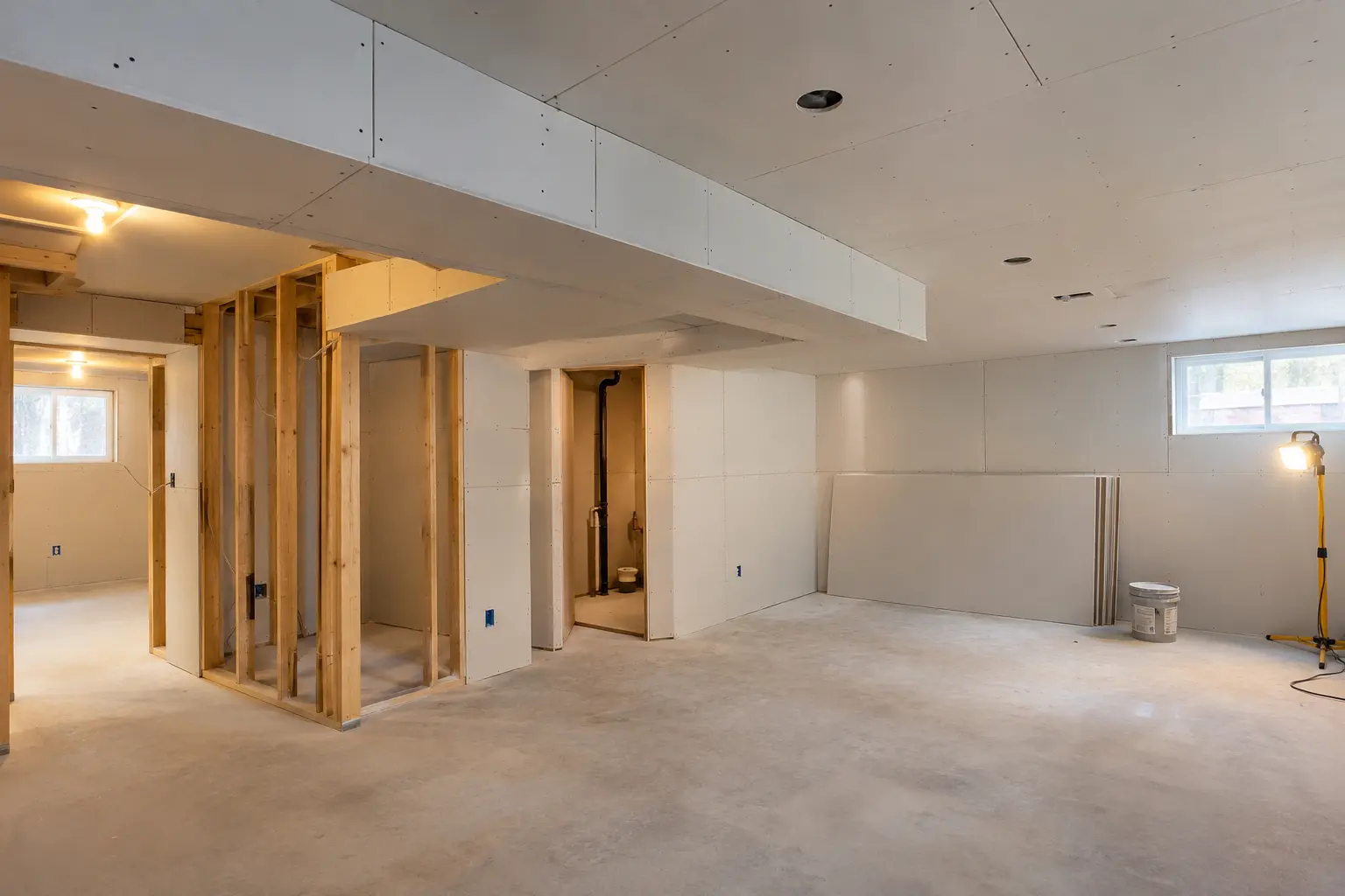
Fire separation is not simply a layer of drywall. The performance of the boundary depends on the complete assembly—framing, layers, joints, supports, doors where applicable and the way pipes, ducts, wires and access panels pass through it.
For an existing basement, the visible ceiling finish may not reveal what lies above it. Permit records, drawings and selective investigation can help establish whether the construction matches an approvable detail or requires correction.
REVIEW THE COMPLETE BOUNDARY
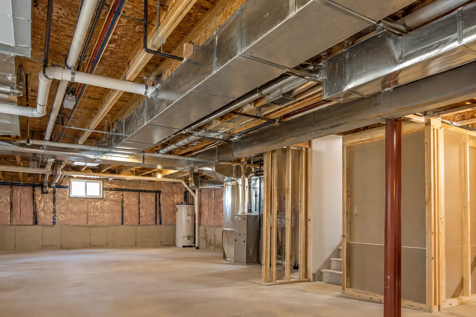
Where Separations Commonly Become Complicated
- Open joist spaces
- Beams and bulkheads
- Plumbing and drain penetrations
- Supply and return ducts
- Electrical boxes and cables
- Recessed fixtures
- Doors and frames
- Mechanical-room access
- Stair and shared-space conditions
- Existing patches and alterations
- Ceiling transitions
- Unfinished storage areas
The design should use verified, context-appropriate assemblies. One fire-rating value cannot be applied universally because building age, configuration, alterations and applicable provisions can change the solution.
FIRE SAFETY AND SOUND CONTROL
Coordinate Overlapping Goals Without Confusing Them
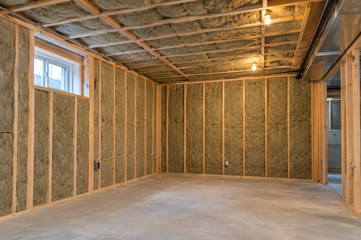
Insulation, resilient components, sealants and multiple board layers may contribute to acoustic comfort, but the approved fire-separation detail must remain clear. Substituting materials or changing the installation sequence can affect the assembly.
Sound control also depends on flanking paths through ducts, doors, structure and service openings. The best time to address those paths is before the ceiling and walls are closed.
ALARMS, SYSTEMS AND INSPECTIONS
Keep Safety Work Visible Until the Correct Stage
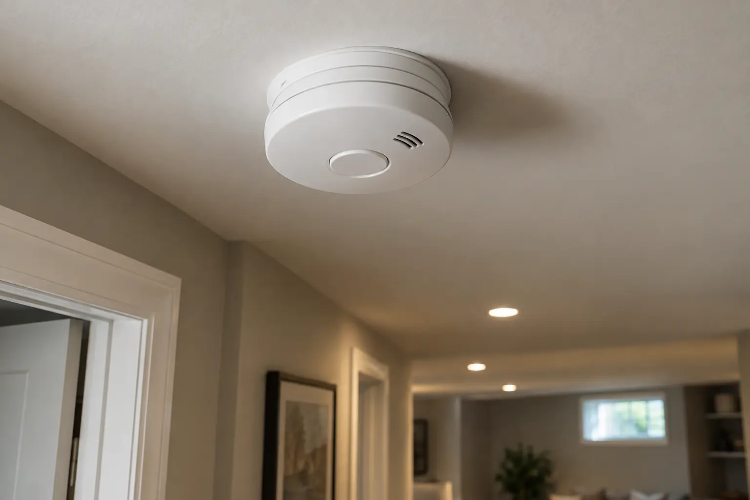
Alarm placement and electrical work should be coordinated with the floor plan and ceiling design. HVAC routes should avoid improvised openings after the fire-separation work is complete. Inspection access should remain available until the relevant work has been reviewed.
Photographs can support project records, but they do not replace required inspections or approved construction details. The goal is a traceable sequence from drawings to installed work to final completion.
QUESTIONS HOMEOWNERS ASK
Frequently Asked Questions
Sometimes records and visible details provide useful evidence, but concealed assemblies and penetrations may require selective openings. The necessary level of investigation depends on the existing work and approval path.
No. Some materials and assemblies can support both goals, but acoustic performance and fire-resistance requirements are not interchangeable. The approved assembly and installation details control the safety function.
Yes. Service penetrations, ducts, bulkheads and access panels can interrupt a separating assembly. They need to be coordinated in the design and installed with the applicable details.
Alarm locations, power, interconnection and the relationship between dwelling areas should be reviewed for the specific project and applicable requirements. Do not treat alarms as a substitute for the required assemblies.
CONTINUITY IS THE DESIGN
Fire Separation Depends on Every Edge and Opening
Boards and insulation matter, but an assembly is only as reliable as its transitions at walls, floors, ducts, pipes, wiring, doors and service spaces. The project needs a coordinated boundary, not a collection of unrelated fire-rated products.
Map the boundary
Identify which walls and ceilings separate units or connect to shared spaces. Trace the assembly continuously through closets, bulkheads and mechanical areas.
Control penetrations
Coordinate every service opening before board installation. Improvised holes after inspection can undermine otherwise careful work.
Keep records
Record approved details, products, installation stages and accepted changes. Photographs support the file but do not replace inspections.
TRADE COORDINATION
Sequence Safety Work Before the Ceiling Is Closed
Mechanical, plumbing and electrical layouts should be settled while framing remains accessible. Large ducts, recessed fixtures, drain piping and structural members can force changes to the separation. A coordinated reflected-ceiling and service plan reduces late penetrations and fragmented bulkheads.
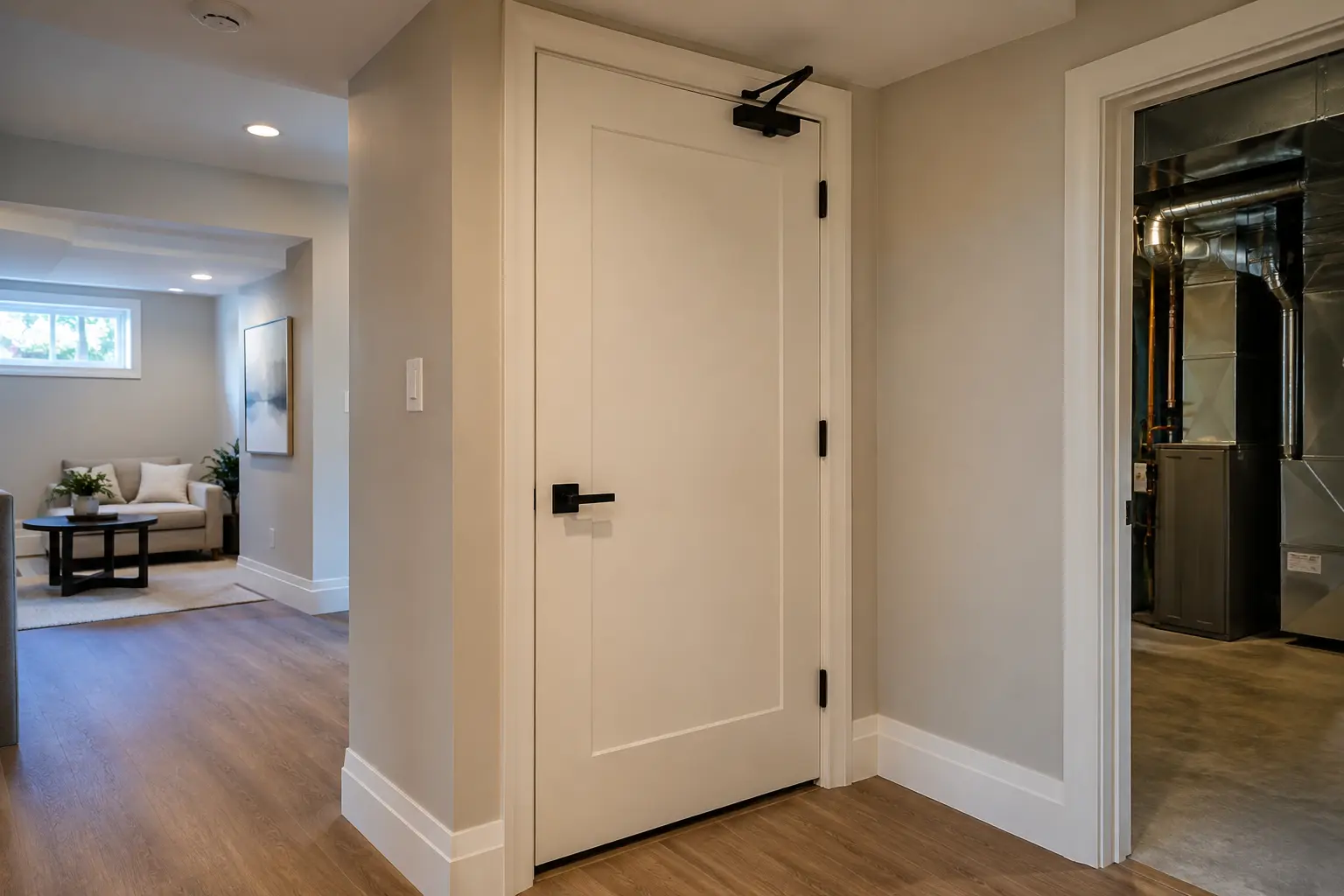
Doors need the correct assembly, frame, hardware and installation details for their location. Service rooms may need particular access and protection. Do not assume a heavy-looking door or fire-labelled product automatically creates a compliant opening when the surrounding construction is incomplete.
Alarm placement should reflect the approved plan and current requirements. Electrical supply, interconnection and device location need to be confirmed by the responsible professionals and trades. Alarms are a critical layer, but they do not replace separation, safe exiting or mechanical design.
Pre-close review questions
- Is the boundary continuous behind ducts and bulkheads?
- Are joints, edges and fastener patterns ready for review?
- Are listed penetration systems matched to the actual service?
- Have dampers or other mechanical measures been coordinated where required?
- Are doors, frames and self-closing functions appropriate?
- Can inspectors see the work at the required stage?
- Do site conditions still match the approved details?
Coordinate acoustic goals through the fire-separation scope rather than adding layers independently. The HVAC service explains why duct paths and room airflow must be resolved at the same time.
SOUND CONTROL WITHOUT GUESSWORK
Reduce Direct and Flanking Paths
Comfort between dwellings depends on more than filling joist cavities. Sound can travel through framing, ducts, doors, stairs, recessed fixtures and continuous finishes. A useful acoustic strategy combines absorption, decoupling, mass and careful sealing while remaining compatible with the approved fire and mechanical design.
Discuss expectations honestly. Footfall, voices, television and mechanical noise behave differently, and perfect silence is not a realistic promise. Prioritize bedrooms, shared ceilings, service rooms and other sensitive adjacencies. Construction quality at edges and penetrations often matters as much as the nominal product specification.
Before handover, test doors and alarms, verify visible penetrations are complete and keep access to equipment. Retain photographs and the current drawing set so future repairs do not unknowingly compromise the separation.
REPAIRS AND FUTURE ALTERATIONS
Protect the Assembly After Handover
Future cable, plumbing or ventilation changes can compromise a separation that was complete at inspection. Keep drawings and concealed-work photographs available, label important access points and tell future trades that walls and ceilings may form part of an approved assembly.
When a leak or repair requires an opening, document the existing layers before removal and restore them using a reviewed detail. Do not fill an unfamiliar penetration with a random foam or sealant based only on colour. Products and systems need to match the actual construction and service.
Owner maintenance observations
- Doors that no longer close or latch reliably
- Damaged ceiling or wall surfaces
- New unsealed openings around cables or pipes
- Missing alarm devices or recurring trouble signals
- Loose grilles, access panels or service-room components
- Water damage affecting protected construction
Prompt review of these conditions helps preserve both safety and the integrity of the project record.
Review the Entire Boundary Before Final Finish
Complete a room-by-room walk before prime paint. Look above cabinets, behind equipment, inside closets and around bulkheads, ducts, pipes, boxes and access panels. Compare the site with the current details and deficiency log. Repeated conditions should be reviewed as a system rather than closed one at a time.
After corrections, keep photographs keyed to the plan and preserve product records where relevant. Final surfaces should not hide open questions. The closeout file needs to show which revision was built and which inspection resolved each material comment.
This boundary review also protects sound-control work. Unsealed edges and flanking paths can reduce acoustic performance even when the main field of wall or ceiling appears complete. Note any future access panels or removable components in the owner record.
REQUEST AN ASSESSMENT
Review Basement Fire-Separation Work
Share the current condition, the result you want and any drawings, permits or inspection information already available.
Project requirements depend on the property, existing conditions and proposed scope.
Discuss Your Basement
Tell us what exists today and what you want the lower level to become.
Please return shortly to request a basement assessment.